China Best How to Fix a Tool Changer Jam?

Time:2026-10-01 Author:Sophia
0%

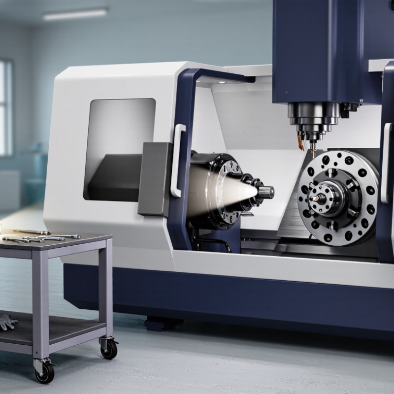
A tool changer jam can stop a machining center without warning. One moment, the spindle is cutting smoothly. Then, an arm freezes beside the magazine, holding a tool halfway through its movement. The question, “China Best How to Fix a Tool Changer Jam?” deserves a careful, practical answer. This guide explains how to fix a tool changer jam on a machining center while protecting the machine, tooling, and operator.

The safest approach begins with the machine manual, alarm history, and a controlled inspection. Stop automatic operation, isolate energy sources, and confirm that stored pressure cannot move the changer. Never force the carousel or pull a tool from a locked gripper. Check for broken tools, chips around the pocket, damaged fingers, incorrect tool position, and low pneumatic pressure. Small metal chips can block a sensor or prevent full seating. A flashlight often reveals more than a rushed adjustment.

Not every jam has the same cause. A misaligned arm may look like a sensor failure. A weak cylinder may imitate a control problem. The first diagnosis is not always right. Record the arm position, alarm code, and visible damage before resetting anything. If the mechanism moves unexpectedly, stop and contact a qualified service technician. Manufacturer procedures differ, and bypassing interlocks can create serious hazards. After repair, test the changer without a cutting tool, then run a slow tool-change cycle. It may feel excessive. It is safer than trusting one successful movement. Proper cleaning, lubrication, alignment checks, and scheduled inspection can prevent the next jam.
China Best How to Fix a Tool Changer Jam?

Diagnose ATC Alarm Codes and Identify the Failed Tool-Change Step

China Best How to Fix a Tool Changer Jam?

An ATC jam is rarely solved by pressing Reset repeatedly. Start with the alarm code, machine position, and last confirmed movement. The failed step may be spindle orientation, tool unclamping, arm rotation, or tool-pot movement. Record the code before clearing it. A disappearing alarm can hide the real sequence failure.

Check the tool-change ladder or diagnostic screen. Confirm whether the unclamp sensor changes state. Then inspect the arm position sensor, gripper fingers, drawbar, and tool pocket. A metal chip under a proximity sensor can create a false signal. The U.S. Department of Energy’s Operations and Maintenance Best Practices guide promotes condition-based checks because visible symptoms often appear before major failure. That principle fits ATC troubleshooting well. Small signals matter.

Do not force the carousel by hand. Isolate power according to the machine’s service procedure, then remove chips and inspect for bent holders or damaged tooling. The 2024 State of Smart Manufacturing report surveyed 1,560 manufacturers and reported broad investment in connected maintenance systems. Data helps, but it does not replace a careful physical inspection. I have seen technicians blame the motor when a worn sensor caused the stop. That assumption wastes time. Recheck the sequence. After repair, run a single empty tool-change cycle, then test with a light tool. Keep the failed code, position, and corrective action in the maintenance record. Mistakes happen. Poor records make them repeat.

How to Fix a Tool Changer Jam: Diagnose ATC Alarm Codes and Identify the Failed Tool-Change Step

The chart shows typical reference times for the main steps in an automatic tool-change cycle. A noticeably longer step can help identify where a jam occurs: spindle orientation and tool release problems usually point to positioning or unclamping faults, while extended arm rotation may indicate mechanical obstruction or incomplete confirmation signals.

Apply ISO 14118 Lockout Procedures and Release Residual Air Pressure

China Best How to Fix a Tool Changer Jam?

A tool changer jam can hide dangerous stored energy. Follow ISO 14118 principles before touching the mechanism. Stop the machine through its normal control, then identify every energy source. Isolate electrical, pneumatic, hydraulic, and gravity-related energy. Apply personal locks and warning tags according to your site procedure. Never depend on an emergency-stop button alone.

Residual air pressure often keeps grippers, cylinders, or clamps under load. Close the pneumatic isolation valve, then bleed air through the designated exhaust point. Watch the pressure gauge until it reaches zero. Confirm that trapped pressure has actually discharged. A gauge can mislead if a blocked line remains pressurized. Secure suspended or spring-loaded parts with suitable mechanical supports. Try the normal start command only after isolation, keeping clear of moving components. The machine must not respond.

Tips: Check the service manual for the approved manual-release method. Do not force the carousel or strike the tool holder. Use eye protection and keep hands outside pinch points. A common mistake is treating the jam as purely mechanical. That assumption can be wrong. If the mechanism still resists movement, stop and request assessment from a qualified technician. After repair, inspect guards, remove tools and supports, restore pressure gradually, and test the changer at low speed. Recheck the sequence.

China Best How to Fix a Tool Changer Jam? - Apply ISO 14118 Lockout Procedures and Release Residual Air Pressure

A practical, machine-neutral workflow for safely diagnosing and releasing a jammed automatic tool changer. Always follow the machine manufacturer’s instructions, site lockout/tagout rules, and the risk assessment for the specific installation.

Step Work Stage Recommended Action Required Verification Main Hazard Controlled Suggested Record
1 Stop and assess Stop the automatic cycle using the normal stop control. Keep clear of the tool carousel, gripper arm, spindle, and moving axes. Identify whether the jam occurred during tool pickup, tool release, carousel rotation, or arm return. The automatic cycle has stopped and no person is inside the machine’s hazardous zone before isolation begins. Unexpected movement, crushing, shearing, and falling tools. Alarm message, machine position, tool station, and visible symptoms.
2 Identify energy sources List all relevant energy sources: electrical power, pneumatic supply, hydraulic pressure if fitted, gravity or elevated components, stored spring force, rotating inertia, and possible tool or workpiece movement. The isolation plan covers primary energy and every secondary or stored-energy source. Re-energization, pressure release, gravity motion, and stored mechanical force. Energy-source checklist and isolation points.
3 Notify affected personnel Inform operators, maintenance personnel, and anyone working nearby that the tool changer will be isolated and serviced. Restrict access to the work area. Affected personnel acknowledge the shutdown and understand that controls must not be operated. Uninformed restart or interference with the machine. Names or roles notified and time of notification.
4 Isolate primary power Open the machine’s main electrical disconnect or other designated energy-isolating device. Apply an individual lock and warning tag in accordance with the site lockout procedure. The isolator is in the safe or off position, and the lock and tag identify the person responsible for the work. Electric shock and electrically powered actuator movement. Isolation device, lock identification, and responsible person.
5 Isolate compressed air Close the designated pneumatic isolation valve upstream of the tool changer or machine pneumatic circuit. Lock and tag the valve where the installation permits. The isolation valve is closed and cannot be reopened without removing the authorized lock. Pneumatic cylinder movement and sudden release of compressed air. Valve location, valve position, lock identification, and time.
6 Release residual air pressure Operate the designated dump or exhaust valve slowly while standing clear of ports and moving components. If no dedicated dump valve exists, use the approved machine-specific method. Never loosen a hose, fitting, or cylinder connection to vent pressure. The pneumatic pressure indicator, if fitted, reads zero. Listen for the exhaust to stop and confirm that actuators no longer respond to authorized controls. Hose whip, flying debris, unexpected gripper or arm movement, and stored pressure. Pressure reading before and after venting; exhaust valve used.
7 Dissipate other stored energy Secure elevated or suspended parts, allow rotating components to stop, discharge applicable electrical storage devices using approved procedures, and control spring-loaded mechanisms. Do not rely solely on the emergency-stop function. No movement, rotation, pressure, or other hazardous stored energy remains, or positive restraints are installed. Gravity drop, spring release, residual rotation, and electrical storage. Restraints installed and stored-energy checks completed.
8 Verify zero energy Attempt a normal start from the operator controls only after confirming the area is clear and the attempt is permitted by the site procedure. Return controls to neutral or off. Use suitable test instruments by qualified personnel where electrical verification is required. No axis, spindle, carousel, gripper, or tool-release mechanism moves. Electrical and pneumatic readings are at the required safe state. Failure of isolation and unexpected startup. Zero-energy verification result and tester identification.
9 Inspect the jam Examine the tool holder, gripper fingers, retention mechanism, carousel pocket, alignment features, sensors, stops, and chips or foreign material. Look for tool misalignment, damaged components, contamination, or an incomplete clamp/unclamp position. The obstruction and probable cause are identified before force is applied. Pinch points, sharp edges, dropped tools, and damage caused by uncontrolled force. Photographs, component condition, and probable failure mode.
10 Release the jam safely Use the approved manual-release, handwheel, maintenance mode, or mechanical recovery method specified for the machine. Support the tool or arm before releasing a clamp. Use non-damaging tools and keep hands outside pinch points. The tool changer is mechanically stable, the tool is supported, and no component can move unexpectedly during release. Crushing, tool drop, sudden arm movement, and component deformation. Recovery method used and parts removed or replaced.
11 Clean and correct the cause Remove chips and contamination using an approved method. Check alignment, fasteners, sensors, air lines, fittings, gripper wear, and tool retention surfaces. Replace damaged parts and correct the underlying setting or maintenance issue. The tool changer reaches its defined clamp, unclamp, home, and index positions without binding. Repeat jam, tool ejection, sensor failure, and mechanical damage. Root cause, corrective action, replaced parts, and inspection results.
12 Restore and test Confirm guards and covers are refitted, tools are secured, personnel are clear, and all tools and temporary restraints are removed. Restore energy according to the authorized procedure, then perform a controlled single-cycle test at reduced risk. The tool changer completes pickup, release, carousel indexing, and return-to-home functions without abnormal noise, leakage, or alarm. Restart movement, ejected tools, unexpected cycling, and exposed moving parts. Test cycle, alarms cleared, leakage check, and final status.
13 Return to service Remove locks and tags only by the persons who applied them, or under the site’s documented authorized process. Notify affected personnel before normal operation resumes. All personnel are clear, guards are functional, and the machine is released by an authorized person. Uncontrolled restart and exposure to moving equipment. Lock removal, notification, authorization, and return-to-service time.
Safety note: ISO 14118 focuses on the prevention of unexpected start-up. It does not replace applicable local lockout/tagout legislation, electrical safety requirements, pneumatic-system procedures, risk assessment, or the machine manufacturer’s recovery instructions. Only trained and authorized personnel should perform the isolation, verification, and repair.

Check ATC Air Supply Within the Typical 0.5–0.7 MPa Operating Range

China Best How to Fix a Tool Changer Jam?

A tool changer jam often starts with unstable air pressure. Check the ATC air supply before forcing any mechanism. The typical operating range is 0.5–0.7 MPa. Read the gauge while the changer is idle and during a tool-change command. A static reading may look normal, yet pressure can drop sharply under demand. Inspect the regulator, filter, tubing, and fittings for leaks. Listen for a faint hiss near the valve manifold. Low pressure may prevent the drawbar from releasing fully. Excessive pressure can also damage seals or create unsafe movement. Disconnect electrical power and bleed stored air before touching components.

Tips: Clean the filter bowl and drain moisture regularly. Verify the gauge against a calibrated test gauge when readings seem doubtful. Check whether the compressor supplies enough flow, not only enough pressure. A blocked muffler can restrict exhaust and slow the cylinder. Mark the original regulator setting before adjustment. Small changes matter.

Do not repeatedly command the changer while it remains jammed. That can bend holders or stress the drive mechanism. After restoring pressure, test the release and clamp cycles without a tool. Watch for delayed motion, unusual noise, or incomplete clamping. I have seen technicians replace sensors too early, while a leaking tube caused the real fault. Still, pressure is not the only possible cause. Mechanical alignment, chips, worn seals, and sensor position deserve inspection if the jam returns. Keep a record of pressure readings and symptoms; memory is often less reliable than a simple note.

Inspect the Gripper, Tool Pocket, Drawbar, and Spindle Orientation

China Best How to Fix a Tool Changer Jam?

A tool changer jam often begins with a small alignment error. Start by stopping the machine and following its isolation procedure. Inspect the gripper fingers for chipped edges, uneven wear, or trapped metal chips. A damaged gripper may hold a tool tightly but release it poorly. Check the tool pocket next. Look for bent retainers, worn liners, and chips beneath the tool flange. Even a thin chip can change the tool’s seating height.

Inspect the drawbar and measure clamping force with approved equipment. Do not judge force by sound alone. Low force can leave the tool loose, while excessive force may overload the release mechanism. The spindle must also reach its commanded orientation. Check the orientation sensor, coupling, and alignment marks. A spindle stopping only a few degrees away can make the gripper strike the holder. In field service, I once blamed the pocket first, but the real fault was a drifting orientation switch. That mistake cost time. It also showed why visual checks are not enough.

The U.S. Department of Energy’s Operations and Maintenance Best Practices guide reports that predictive maintenance can save 8–12% over preventive maintenance. McKinsey reports that predictive maintenance may reduce machine downtime by 30–50%. Record drawbar force, orientation offset, and pocket wear during scheduled checks. Test the changer at low speed with an empty spindle, then use a verified tool holder. Never force the carousel by hand. One overlooked chip can return tomorrow.

Validate 10 Consecutive Tool Changes Against ISO 230-2 Repeatability Data

A tool changer jam should be treated as a repeatability problem, not only a mechanical obstruction. Stop the machine safely and inspect the pocket, gripper arms, taper, and chip guards. Look for packed chips, uneven wear, or a tool that sits slightly higher than its neighbors. Record spindle orientation, unclamp pressure, and transfer time before adjusting anything. Small changes can hide the real fault.

After cleaning and inspection, run ten consecutive tool changes with the same approved test holder. Use a calibrated indicator or probe to check tool seating and repeatable position after every cycle. Record each result, including failed transfers, unusual sounds, and delayed clamp signals. Compare the measurements with the machine’s ISO 230-2 positioning repeatability data. ISO 230-2 does not replace a tool changer test, but it provides a useful reference for axis-related movement and repeatability.

The spread between the ten readings matters more than one excellent result. A single high value may indicate contamination, pressure loss, or an inconsistent release sequence. Recheck the test after the machine reaches operating temperature. I have seen clean mechanisms fail after warm-up. That detail is easy to miss. If results remain unstable, verify sensor timing, pneumatic pressure, arm alignment, and parameter settings with qualified maintenance personnel. Do not simply increase force; it may damage the holder or conceal a worn component. Keep the raw data, photographs, and correction history for future audits.

FAQS

What should I record before clearing an ATC alarm?

Record the alarm code, machine position, and last confirmed movement. A disappearing alarm can hide the failed sequence.

Which tool-change steps commonly cause a jam?

The failure may involve spindle orientation, tool unclamping, arm rotation, or tool-pocket movement. Check the sequence, not just the visible jam.

How can I identify a false sensor signal?

Open the diagnostic screen and watch the unclamp and arm-position sensors. Remove chips near proximity sensors. One small chip can create a false signal.

What physical parts need inspection after safely isolating power?

Inspect the gripper fingers, drawbar, tool pocket, arm, taper, and chip guards. Look for bent holders, packed chips, uneven wear, or a raised tool.

Should I force the carousel or tool arm by hand?

No. Follow the machine’s service isolation procedure before removing chips or inspecting mechanisms. Hand force may damage the arm or hide the real fault.

How should I test the tool changer after cleaning and repair?

Run one empty tool-change cycle first. Then test with a light, approved holder. Watch seating, sounds, transfer time, and clamp signals.

Why are ten consecutive tool changes useful?

Ten cycles reveal inconsistent behavior better than one successful cycle. Use the same test holder and record every result. A perfect first cycle proves little.

What measurements should I take during repeatability testing?

Use a calibrated indicator or probe to check tool seating and position after each cycle. Record failed transfers, delayed signals, unusual sounds, and reading spread.

What should I compare the test results with?

Compare the readings with the machine’s positioning repeatability data under the applicable international standard. This reference helps evaluate axis movement, but it does not replace a tool-changer test.

What if the tool changer works cold but fails after warm-up?

Recheck the ten-cycle test at operating temperature. Then verify sensor timing, pneumatic pressure, arm alignment, and parameter settings. Do not simply increase force. That shortcut may damage the holder.

Conclusion

Fixing a tool changer jam on a machining center begins with a controlled diagnosis rather than forceful intervention. Review the ATC alarm codes and determine which stage failed, such as tool release, arm movement, pocket positioning, or spindle orientation. Before inspection, apply ISO 14118 lockout procedures, isolate electrical and pneumatic energy, and release all residual air pressure. Then confirm that the ATC air supply is stable within the typical 0.5–0.7 MPa operating range.

After securing the machine, inspect the gripper fingers, tool pocket, drawbar, and spindle orientation for chips, damage, misalignment, or incomplete movement. Correct the underlying issue and verify that the tool is properly clamped and released. Finally, run at least 10 consecutive tool changes under safe operating conditions, checking smooth motion, alarm-free cycling, and repeatability against relevant ISO 230-2 data. This systematic process explains how to fix a tool changer jam on a machining center while reducing the risk of recurring failures.

Sophia

Sophia

Sophia is a dedicated marketing professional with an exceptional depth of knowledge about her company's products and services. With a keen understanding of market trends and customer needs, she crafts insightful blog posts that not only inform but also engage readers, enriching the company’s online......