In 2026, manufacturers still ask: what causes dimensional inaccuracy in multi axis cnc machining? The answer is rarely one defective component. It usually involves machine geometry, thermal drift, tool deflection, control settings, fixturing, and measurement practice.
ISO 230-2:2014 remains a key reference for testing numerically controlled machine tools. It separates positioning accuracy from repeatability, exposing errors that routine shop-floor checks may miss. NIST research on smart manufacturing also emphasizes traceable measurement, process monitoring, and uncertainty control. These points matter when a 0.02 mm deviation appears after a long titanium cut.
The 2024 World Manufacturing Forum report highlights process stability, digital skills, and data quality as major manufacturing priorities. Those priorities are practical. A warm spindle changes tool-tip location. A thin fixture plate bends during clamping. A long ball-nose cutter deflects near a steep wall. Small errors can combine.
Professor Yusuf Altintas, a leading machining science authority, states, “The main source of machining errors is the cutting force-induced tool deflection.” His point remains highly relevant, although it does not explain every failed part. Thermal expansion and rotary-axis calibration can dominate in other conditions.
This guide examines the top causes behind multi-axis CNC dimensional inaccuracy. It connects engineering theory with inspection evidence, including probing results, gauge records, and machine-tool compensation data. Some assumptions will need challenging. A perfect calibration report does not guarantee a perfect component. Real accuracy depends on the entire machining system, from CAM simulation to final measurement.
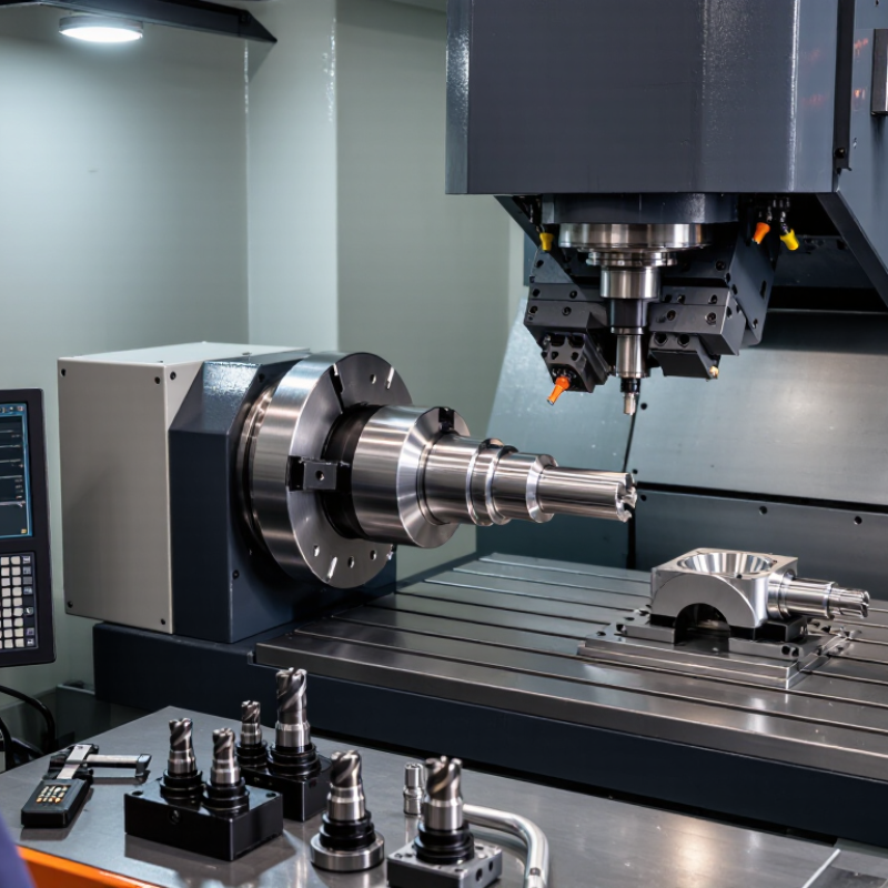
Multi-axis CNC dimensional inaccuracy means the finished part differs from its intended geometry. The error may appear as a wrong hole position, uneven wall thickness, or incorrect angular surface. It is not limited to one measured length. Several axes can combine their errors during a single tool movement.
In practice, I have seen small rotary-axis errors create large deviations at the cutting point. Thermal growth can shift the tool after several hours of machining. Backlash, worn bearings, poor probing, and incorrect work offsets can produce similar symptoms. Tool deflection also matters, especially during deep cuts or heavy engagement. A part may pass a simple height check but fail when its true position is inspected in three dimensions.
Measurement strategy is part of the problem. A loose fixture can move slightly, while an inaccurate reference surface can mislead the entire setup. Environmental temperature should be recorded, not guessed. Calibration data needs careful review after maintenance or an axis adjustment. One imperfect habit is checking only the final dimension. That can hide the movement pattern behind the error. Comparing several datums, probing repeated points, and reviewing machine simulation often reveals whether the fault comes from setup, control data, or machine geometry. Still, inspection results are not always clean. Human judgment can affect probe placement and interpretation.
Meaning: Multi-axis CNC dimensional inaccuracy is the difference between the programmed geometry and the machined geometry when linear and rotary axes work together. It may appear as position error, contour deviation, incorrect feature location, poor angular accuracy, or dimensional drift that changes with machine orientation, temperature, cutting load, or tool length.
| Primary Cause | Typical Engineering Reference Range* | How It Creates Dimensional Error | Most Affected Conditions | Common Observable Symptoms | Recommended Verification or Control |
|---|---|---|---|---|---|
| Thermal growth and thermal gradients | 10–50 µm of linear growth per metre can occur with a 10–25°C temperature change, depending on machine structure and material. | Heat from the spindle, motors, coolant, bearings, and surrounding environment changes the position of the tool centre point and work coordinate system. | Long warm-up periods, long parts, high spindle speed, changing shop temperature, and extended unattended cycles. | Dimensions are accurate at the beginning of a cycle but drift later; errors may reverse after the machine cools. | Record machine and coolant temperature; compare cold and thermally stable measurements; use controlled warm-up, thermal compensation, and stable coolant temperature. |
| Geometric misalignment and axis squareness error | Common machine-tool diagnostic results are reported in micrometres per metre or arc-seconds; the allowable value depends on the machine specification and acceptance test. | Non-squared linear axes, guideway alignment errors, or an incorrectly aligned rotary axis transform programmed coordinates into incorrect tool positions. | Large work envelopes, simultaneous five-axis motion, diagonal cuts, and features located far from the machine origin. | Errors increase with travel distance; circular interpolation becomes elliptical or out of round; diagonal features show position deviation. | Perform laser interferometer, ball-bar, straightness, squareness, and volumetric calibration tests in accordance with applicable machine-tool procedures. |
| Rotary-axis centerline, pivot-point, and angular positioning error | A 0.001° angular error produces approximately 17.5 µm of tangential displacement at a 1 m radius; the error is smaller at shorter radii but remains geometry-dependent. | Incorrect rotary-axis kinematic parameters cause the tool centre point to move along the wrong arc or around the wrong pivot location. | Five-axis simultaneous machining, tilted-plane machining, large tool reach, and features positioned far from the rotary centerline. | Errors change when the part or tool is indexed; holes or surfaces are correct at one angle and displaced at another angle. | Measure rotary-axis positioning and reversal accuracy; calibrate pivot length and rotary-axis offsets using a certified artifact or kinematic calibration procedure. |
| Backlash, lost motion, and servo following error | A reversal-related error may range from a few micrometres to tens of micrometres on a poorly adjusted or worn axis; the actual value must be measured. | Mechanical clearance, thrust variation, ballscrew wear, or servo lag prevents the commanded position from being reached consistently during direction changes. | Contour reversals, quadrant changes, short interpolated moves, worn ballscrews, and high acceleration or feed rates. | Different results occur when approaching a point from opposite directions; circular or corner features show lobing, steps, or mismatch. | Check backlash and bidirectional positioning with a laser interferometer, dial indicator, ball-bar, or calibrated linear measurement system. |
| Tool deflection and workpiece deflection | Deflection can vary from less than 10 µm to over 100 µm, depending on tool overhang, diameter, material, radial engagement, and cutting force. | Cutting forces bend the tool, holder, fixture, or workpiece, so the cutter removes less or more material than the programmed path predicts. | Deep cavities, long slender tools, thin walls, hard materials, high radial engagement, and heavy roughing cuts. | Wall taper, corner oversize or undersize, chatter marks, dimensional change with feed or depth of cut, and spring passes that improve size. | Reduce overhang and radial engagement; compare unloaded probing with cutting results; use cutting-force analysis, adequate workholding, and tool deflection compensation where available. |
| Spindle, tool-holder, and tool runout | Precision finishing systems may target single-digit micrometre runout; worn or contaminated interfaces can produce several tens of micrometres. | Runout changes the effective cutting diameter and causes uneven tooth engagement, which directly affects hole size, surface location, and form accuracy. | Hole-making, reaming, finishing with small tools, high-speed machining, and tool changes between operations. | Oversize holes, uneven tool wear, poor surface finish, periodic marks, and different dimensions after a tool or holder change. | Measure tool-tip and holder runout with a calibrated indicator; clean taper interfaces, inspect pull studs and holders, and verify spindle-bearing condition. |
| Workholding movement, fixture error, and datum instability | Movement may be below 10 µm in a rigid, correctly loaded setup but can exceed 50 µm when clamping, seating, or fixture stiffness is inadequate. | Part movement or inconsistent seating changes the relationship between the workpiece coordinate system and the machine coordinate system. | Thin parts, castings, interrupted surfaces, high clamping forces, multiple setups, and parts with residual stress. | Part-to-part location variation, feature misalignment between faces, distortion after unclamping, and inconsistent probe results. | Verify locating-pin contact and clamp sequence; inspect fixture repeatability; use controlled clamping force, stable datums, and in-process probing. |
| Incorrect tool length, work offset, or kinematic compensation data | A data-entry or probing error can create a direct offset from a few micrometres to several millimetres, depending on the affected parameter. | Incorrect tool length, radius, work offset, rotary-axis pivot, or TCP setting makes the control calculate a geometrically incorrect tool position. | Tool changes, fixture changes, new postprocessors, machine reconfiguration, and simultaneous five-axis programs. | Consistent offset across an entire feature, incorrect dimensions after a setup change, or large errors only when TCP or cutter compensation is active. | Audit offsets against a controlled setup sheet; verify probe calibration, tool measurement, postprocessor settings, TCP mode, and units. |
| Control interpolation, postprocessor, and coordinate-transformation errors | The resulting error is program-dependent and may range from negligible to millimetres if a rotary-axis sign, center, unit, or transformation setting is wrong. | Incorrect axis conventions, inverse-time feed settings, rotary-axis limits, tool-center-point logic, or coordinate transformations generate an incorrect commanded path. | Simultaneous multi-axis programs, converted NC files, machine-to-machine program transfers, and postprocessor revisions. | Errors appear only on specific toolpaths, rotary angles, feed modes, or machines; simulation and machined results do not agree. | Backplot the actual NC code, compare commanded and simulated TCP paths, verify axis direction and units, and test with a controlled calibration program. |
| Cutting-fluid, chip, and contamination effects | A chip or debris layer of only 10–50 µm can be sufficient to change a precision datum or fixture seating condition. | Chips, dirt, coolant-film variation, or poor flushing prevent repeatable contact between the part, fixture, tool holder, or probing surface. | Deep pockets, interrupted cuts, automated loading, high-pressure coolant, and operations with frequent reclamping. | Intermittent dimensional variation, isolated outliers, poor probe repeatability, and errors that disappear after cleaning. | Clean and inspect all datum surfaces; improve chip evacuation; verify probing repeatability before and after cleaning. |
| Measurement-system and inspection uncertainty | The measurement contribution should be small relative to the tolerance; a practical rule is to keep measurement uncertainty at approximately 10% or less of the tolerance where feasible. | Temperature differences, probe qualification, fixturing, alignment, software filtering, and instrument resolution can make a correct part appear incorrect. | Tight tolerances, large parts, hot parts, complex freeform surfaces, and comparisons between machine probing and external inspection. | Conflicting results between the machine probe, CMM, gauges, and manual instruments; repeatability changes with operator or measurement direction. | Use calibrated standards, temperature-controlled inspection, repeatability and reproducibility studies, correct datum alignment, and traceable measurement procedures. |
Note: The numerical ranges are diagnostic reference values rather than universal acceptance limits. Actual dimensional accuracy depends on machine design, axis travel, part size, material, tooling, thermal condition, control configuration, and the tolerance requirement. ISO 230 series and ASME B5.54/B5.57 are commonly used references for machine-tool accuracy, repeatability, thermal behavior, and performance evaluation.
Small angular errors can multiply across several axis movements. A slightly leaning column may shift holes, pockets, and five-axis surfaces.
Misalignment often changes across travel. A dial indicator can reveal deviation at different positions.
Verify straightness, squareness, parallelism, and backlash. Check rotary-axis centerline accuracy carefully. The first reading may be wrong.
Spindle heat, coolant temperature, motors, and room conditions can shift machine geometry. Thermal effects may represent 40–70% of total error.
Measure after the machine reaches a stable operating temperature. One fixed warm-up time is not always reliable.
Backlash, bearing preload, guideway wear, rotary-axis tilt, and disturbed mounting surfaces can combine across movements.
Cutting force bends the tool and may move its tip visibly. A 500 N force on a 100 mm overhang can cause noticeable error.
Record spindle temperature, coolant temperature, axis position, and tool overhang together. A test cut may reveal more than calibration data.
Use a controlled adjustment sequence. Compare several positions, repeat tests, and record before-and-after values. Do not chase one reading.
Multi-axis CNC dimensional inaccuracy occurs when the machined part does not match its intended CAD dimensions, tolerances, or geometric relationships. Understanding what causes dimensional inaccuracy in multi axis cnc machining requires examining several interacting factors. Machine geometry and axis alignment errors can create positioning deviations, rotary-axis inaccuracies, backlash, or squareness problems that become more noticeable during complex tool movements. Thermal expansion from prolonged operation, mechanical vibration, spindle behavior, cutting forces, and tool deflection can further alter the final dimensions.
Programming and setup choices also have a major influence. Incorrect tool offsets, unsuitable feeds and speeds, poor toolpath planning, fixture movement, inadequate workholding, or part deformation can all introduce errors. In addition, inaccurate measurement equipment, weak calibration routines, inconsistent probing, and insufficient process monitoring may allow problems to remain undetected. Reliable results depend on maintaining machine alignment, controlling temperature, selecting stable tools and fixtures, verifying programs, and applying regular measurement and calibration procedures throughout production.

 AcuTek CNC